First: some welcome news. My RPi 3B+ is fine and LibreELEC is back up and running. It was the SD card all along and the earlier Pis were fine. Oh well. I have a spare RPi 3B now...
Now, you’ll remember from the last blog that I complained about having to do 160 solder joints for the next thing I want to make. It’s time to talk about that and see if I can figure out the best way of achieving the right result. I want to try and make my own LED matrix rather than cheat and buy a ready made one. I have to learn this stuff for myself.
By arranging my LEDs in a grid formation with the positive and negative legs arranged into rows and columns it’s possible to make individually controllable LEDs. You can light full rows and columns at the same time, but the opposing states of the lights in a diagonal shape doesn’t work with this process. A column can’t both be set to ground to turn one LED on and not set to ground so the light below doesn’t illuminate. Instead we’ll use a neat trick of the brain to achieve what we need to make complex shapes on the display.Enter: multiplexing.
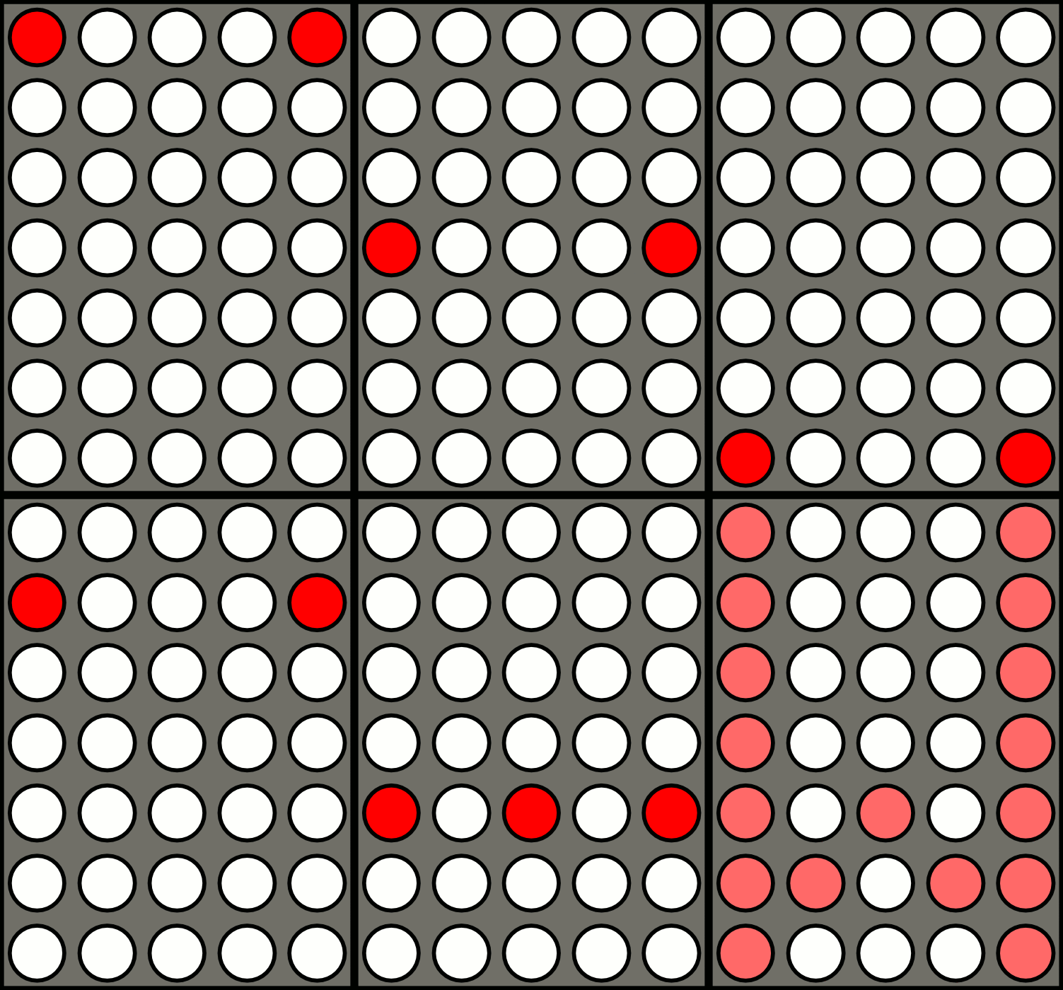
We’ll be able to turn our lights on and off very quickly, one row at a time, hopefully quick enough so that the human brain won’t notice. The RPi3 and some interpreted Python should be fast enough to do that, but you’d get better refresh rates from something like an Arduino I’d wager. To do this I’ll need to write some code to actually parse through some list of lights to illuminate. You’ll see from this gif that I stole from Wikipedia how it works in practise. Of course I’ll need to get a decent amount (50-100) of LEDs, and I’m gonna go with the classic red colour. They’ll have a forward voltage of around 3.0-3.3V so I’ll need a resistor for driving each row of LEDs. 220-330 Ohm should be fine. I also want to get a female header connector and try and make a much better designed cable for connecting the board to the Pi. Individual jumper wires are an absolute mess. Finally I’ll need to get some perfboard for this as the stripboard is hard to work with for this kind of project. There’d be a lot of tracks to break and it’s easier to join the LED legs directly together. So I’ll buy a stack of them at a decent size. One thing that has to change: no more soldering directly on a surface. It bends everything and is a real pain. Instead I’m ordering a little clamp gadget that will hold the board for me. Bending the legs below the board will hold them in while it’s upside down, and they need to be connected anyway.On the software side I’ll be using Python for this and there are several good code fragments I could look at, but if I’m using simple GPIO pin output I can just do it raw for now. If I convert the circuit to work with a shift register or a purpose-built LED controller then I can use a handy library or two.
Essentially there will be a loop that turns on each row and then turns on each column as required to light the LED at that position. By doing in this in order for each light at a fast enough rate we’ll get the effect we’ll need and the brain will be tricked.
I should think about maybe sticking this in a box, so I’ll see about finding some sort of enclosure, but the perfboards come with screw holes in the corners so some stand-offs should do it and can screw into basically anything. Or I could put this board into another project later on and combine it with other things.
So, a lot to consider. I’ll get started in Part 6.
 Skip to main content


Comments
Post a Comment