I think we all had this growing up, right? Those of us of a certain age, anyway.
I decided to remake this for the RPi using some buttons and LEDs and one of my prototype boards, but this time I didn’t want an ugly mess sticking to one side of the RPi. I also needed some soldering practise.
So instead of using a mass of cables to connect the board I decided to solder a 40-pin header connector directly onto the prototype board. This meant I also needed to find some standoffs to hold the board steady and clear of the RPi. This would be a lot sturdier as well when pushing the buttons on top. Essentially I’m making a custom HAT.
The only issue is the size of the prototype board I’m using, which is nowhere near the right dimensions to ensure stand-offs would fit through the holes on the RPi. Because of this lack of adherence to physical specifications it technically can’t be called a HAT. But fuck that. It’s a problem that will need solving though, but we’ll cross that bridge when we come to it. I could have bought the right size board from somewhere, but I just got carried away and got stuck in, as usual.
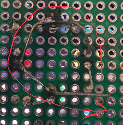
Here’s the basic layout (taken much later in the process, you'll notice). With 4 LEDs and resistors plus 4 buttons on each side this was a challenging layout, with space needed to accommodate the 40 pin connector as well. Using all four of the buttons is possible, but I had to really space things out so that you didn't inadvertently touch something else. Commence soldering! One of the things that helped to save space and cabling was to use a common ground pin for all of the LEDs, so I made this nifty loop of daisy-chained cathode pins. It worked well and I was able to keep it at quite a low profile by smushing it down. I could also have brought them to a single point on the board and connected that to GND. And here’s the header connector soldering, which I genuinely think was okay on the whole, and I can’t see any major spillages. Concentration++. I think I can definitely see an improvement in some soldering work, but then when things get too complex (multiple things joining at once) or there's no room to work it gets messy fast. I need to be a bit better at feeding the right amount of solder in with my other hand. Sometimes I do too little because I worry about ending up with a huge ball of it, so I end up making a joint with barely any solder in it, or in some cases it just evaporates into the air and I "lose" it... And it fits! It felt really snug and was quite satisfying. A little TOO snug if my early attempts to take it off again were anything to go by. I tried to lift it up on each side, a bit at a time, but doing that with any great force made some of the header pins on the RPi get a bit bent. So now the trick is to only *gently* nudge it up on each side, taking much longer overall. That way it comes off evenly and you don't mangle something. What are real HATs like? Are they as tough to get back off again? With everything attached it was time to do the wiring. This time we’re stripping off much less insulation for an electrically “safer” connection with less chance of short circuits. I aimed to poke wires through the holes from the back to attach them to the header pins and solder them on the top. It’s the only way to do it really, with the connector being effectively “upside down” on the board if you think about it.Doing the other side of the wires was done underneath, obviously. This is where it got tricky. I once again - as with the LED matrix - tried to route cables neatly, with some early success. It was when I had no choice but to cross things over that I had an issue. It quickly became a bit of a mess, but the mouldable cables meant I could squish them down and bend them around things and it seemed to help. When plugged in to the RPi there was nothing touching where there shouldn’t be.
I also needed to make a little power rail to feed out +3.3V to the buttons so that I could detect the relevant GPIO pins going high when they were pushed. I broke this out to a corner of the board rather than attempting to solder 4 wires to one pin through a single hole...
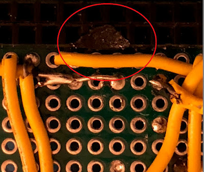
Now: there was a major snag at this point. Somehow, with an errant flick of the arm, I had managed to absentmindedly burnt the edge of the header connector with my soldering iron, melting it completely and ensuring that it would no longer work as a plug for the RPi header pins. You can see from the picture just how messed up it was.Luckily I had my stripboard track break tool, which is essentially a hand drill. I was able to make the holes more... hole again, and then plugging the board in did the rest. I quickly finished the rest of the cabling and tested all the joints for continuity.
And here’s the finished article, attached to my RPi3. This should be quite easy to code for, just interacting with single I/O pins and writing some simple game logic. I’ll have a go soon. But for next time... it’s time to code the matrix... Skip to main content


Comments
Post a Comment